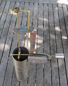
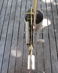
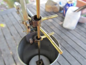
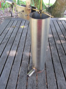
The float mechanism currently used in conjunction with the control units consists of a float cylinder connected to the stirrer via a pipe and top mount, a float guide, adjustments lugs, and mount for micro switch with counter weight.
This or a similar system to sense vortex of the stirrer will need to be constructed to be used in conjunction with the control units – the float mechanism is recommended and has been tested working in the field for over a decade.
The construction is simple and effective for sensing the height of the stirrer vortex and signalling the control unit to stop the motor at the height of the vortex and start the motor again as the float falls.
These images depict a new stainless steel mechanism to be fitted to a stainless steel stirrer, the float can also be constructed from copper and fitted to a copper stirrer as shown in a working unit further down the page.
NB: Detail and construction images open to full size view in a new tab/window.
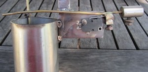
The float, float guide, and counter weight arm are brass brazing rods. The counter weight is alloy and weighs approximately 40 grams.
A recommended micro switch is Jaycar Electronics part number SM1040 and can be supplied with control units if requested. Other micro switches can be used – they should have a solid and considerable length of travel between on/off, some are very fine and require slightest of movement to trigger – these are not recommended.
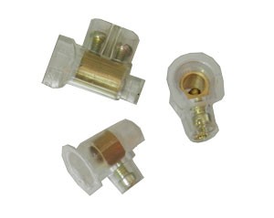
The adjustment lugs are the brass sheath and screw from insulated power connectors with the plastic casing cut away.
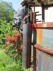
The float body is secured to the stirrer via the pipe which fills the float as the vortex rises, and a bracing plate at the top (circled in red).
The height of the float mechanism should be such that the inlet tube at the bottom is at the same or slightly lower than the water level when the stirrer is full and at idle.
Keep in mind (especially with stainless steel) the bracing plate needs to allow the float mechanism to be adjusted by flexing the float body left-right horizontally in relation to the stirrer in order to fine tune operation.
Once assembled the counter weight and arms which trigger motor stop and start can be easily adjusted by loosening the adjustment lugs and moving the counter weight and position of the arms. The top arm should sit just above the micro switch arm when the float is low, the bottom arm will be 25-30mm below this and is adjusted as necessary to tune the stirrer.
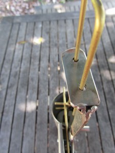
The micro switch cover plate helps keep the switch mechanism clean but should allow unhindered arm movement during the stirring cycle. The float guide rod ensures the float doesn’t rotate during operation and the micro switch arms stay inline to trigger the counter weighted switch.
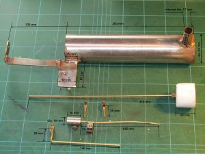
The following blow-out details the components required to be built for the float mechanism to be modified or added to an existing or new stirrer.
The float itself is secured to the rod by brazing a disc to the bottom of the rod, inserting the rod through the float, and placing another disc at the top that has a small center hole, then securing it in place with an adjustment lug.
